Production principle of road and Bridge

1. Overview and requirements
1.1. Overview
Production practice plays an important role in connecting learning and construction. By visiting and personally participating in the construction, we can learn a lot of things that we can't learn from books and improve our ability to integrate theory with practice.
The internship lasts for 10 days from August 16, 2021 to August 25, 2021. During this period, the teacher led us to visit and study the bridge structure, slope retaining wall protection treatment, bridge pile foundation construction and pouring, urban road asphalt structure, asphalt paving process, liangwangshan tunnel construction and other contents in turn. During the visit, the teacher organized us to discuss and answer questions, and everyone gained a lot.
1.2. requirements
Before the internship, organize a mobilization meeting. The teacher introduces the purpose and requirements of the internship, the main internship contents and time arrangement, and the matters needing attention in the internship, with special emphasis on the safety precautions in the internship.
Contents of knowledge required to be mastered by students during practice:
- Master the subgrade and pavement construction of expressway, the design and construction characteristics, methods and processes of bridges and other highway related facilities, deepen the understanding of the course knowledge, and combine theory with practice.
- Familiar with technical standard system, intellectual property rights, industrial policies, laws and regulations related to road and Bridge Specialty;
- Familiar with the construction management process of road and bridge engineering projects. Be able to analyze and formulate the construction project process and scheme by using the basic theories related to roads;
- Be able to make statements on Relevant Issues in expressway design and construction, clearly express the specific ideas, ideas, schemes, measures and effects of construction or design, and effectively communicate with peers in the industry and the public.
2. Practice content
2.1. Bridge part
2.1.1. Internship time and place (unit)
2021.08.19-Near wanxichong primary school (China Railway 24th Bureau)
2.1.2. Construction and pouring of bridge structure and Bridge Pile Foundation
(1) Bridge structure
In the past, I learned about the types of bridges and the forms of various types from books, as shown in Figure 1. But this knowledge always stays in books. Through this visit to the bridge, I really noticed the actual structure of the bridge, as shown in Figure 2 and figure 3.
Main components of the bridge: superstructure, substructure and auxiliary structure.
The superstructure is composed of bridge collapse structure, bearing system, etc.
The substructure is composed of pier, abutment, pier and abutment foundation, etc
The auxiliary structure is composed of expansion joints, lighting, bridge deck pavement, drainage and waterproof system, crash barrier and other parts.
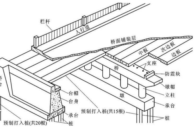
Fig. 1 basic structure of bridge
Expansion joint refers to a structural joint set at an appropriate position along the construction joint direction of buildings or structures to prevent cracks or damage to the structure due to temperature changes (thermal expansion and cold contraction).
![]()
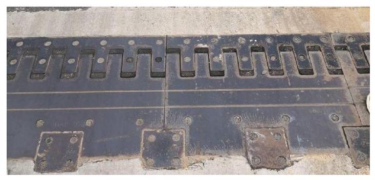
Fig. 2 site drawing of expansion joint

Fig. 3 site drawing of shockproof block, bearing and pier column
(2) Bridge lattice hollowing
At the turning of the bridge, increase the number of lower pier columns and hollow out the upper part of the bridge to reduce the dead weight of the bridge and save materials, as shown in Figure 4.
![]()

Figure 4 bridge hollowing out site
(3) determination of pile driving position - pile casing
The main tool for determining the pile driving position is the pile casing, as shown in Figure 5.
The inner diameter of the pile casing should be larger than the pile diameter
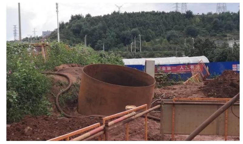
Fig. 5 field drawing of casing
(4) Test the quality of pile - acoustic pipe
The measuring tool of pile driving quality is mainly acoustic pipe, as shown in Figure 6.
The acoustic pipe adopts the acoustic transmission method, and the ultrasonic transmitting probe and receiving probe are respectively lowered into different steel pipes pre embedded in the pile body and filled with water. The ultrasonic generated by the transmitting probe penetrates the concrete of the pile body through water coupling to the receiving probe in another steel pipe, and the receiving probe transmits the received information to the instrument. Analyze the received ultrasonic information in concrete, such as the characteristics of parameters such as sound velocity, sound amplitude, frequency and waveform, and evaluate the quality of pile concrete.
Its basic basis is that when there are defects in concrete, the parameters of ultrasonic sound velocity, sound amplitude, frequency and waveform can be reflected.
![]()
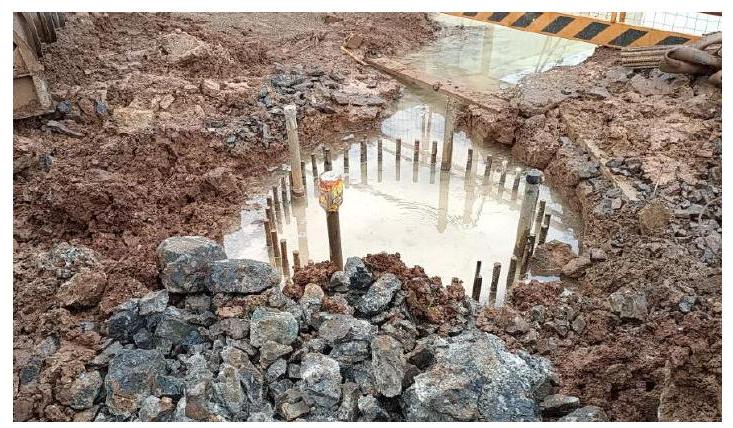
Fig. 6 site drawing of acoustic pipe
(5) Measures to prevent hole wall collapse - slurry wall protection
In order to prevent the hole wall from collapsing, the mud with high density can be pressed into the hole through the hose with stone. Due to the high relative density, the suspended solids in the hole can be replaced and a circulation can be formed.
(6) Reinforcement scattered distribution - ensure safety
When the stressed reinforcement adopts mechanical connection joint or welded joint, the joints set in the same member should be staggered from each other. The position of the connecting joint is the weak link under stress, and staggering can ensure the good performance of the components. As shown in Figure 7.
![]()

Figure 7 field diagram of dislocation of reinforcement connection joint
3. Slope and retaining wall
3.1. Internship time and place (unit)
3.1.1. Slope and retaining wall
(1) Slope
Slope refers to the slope with a certain slope made on both sides of the subgrade to ensure the stability of the subgrade. It is generally used on the rock slope with poor lithology, low strength, easily weathered or hard rock stratum weathered and broken, and its surface weathered and peeled off. Its function is to prevent rainwater scouring, consolidate soil and protect slope, maintain water and soil balance, and maintain the stability of subgrade and slope.
Slope protection mainly includes plant protection and engineering protection. Among them, plant protection includes planting grass, planting trees, laying turf, etc. Engineering protection includes mortar protection, masonry protection, etc.
Suitable for grass planting, the soil slope with small slope height and slope not steeper than 1:1.0 is easy to plant, and the surface water runoff velocity shall be less than $0.6 \ mathrm {~ m} / \ mathrm {s} $. As shown in Figure 8.
When the surface water runoff velocity is between $0.6 \ mathrm {MLS} 1.8 \ mathrm {MLS} $, it is not suitable to plant grass. Instead, the turf shall be paved according to different methods such as tiling and water stacking. If necessary, mortar protection can be carried out first, and the turf shall be paved inside the mortar to reduce water scouring.
Tree planting is mainly used for river beach, desert and protective forest in snow damaged areas on the Bank of embankment.
For mortar protection, the mixed cement and lime mineral mixtures are used to cover and fill the slope. As shown in Figure 9.
Masonry protection can use precast concrete blocks, mortar rubble, etc. as the framework, and plant protection or other auxiliary protection measures can be adopted in the frame. As shown in Figure 10.

Fig. 8 site map of grass planting protection
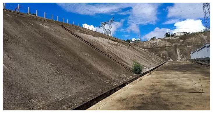
Figure 9 mortar protection

Fig. 10 body protection
(2) Retaining wall
Retaining wall refers to the structure that supports subgrade fill or hillside soil and prevents deformation and instability of fill or soil. It is widely used to support subgrade slope, abutment, bridge head approach and tunnel portal.
According to the different stability mechanism of retaining wall, there are many forms of retaining wall, mainly including gravity retaining wall, cantilever retaining wall, buttress retaining wall and so on. According to the inclination degree of the wall back, the gravity retaining wall can be divided into pitching type, tilting type and vertical type. As shown in Figure 11, Figure 12 and figure 13.
a. The gravity retaining wall is generally made of block stone, brick or plain concrete. It is stable by the gravity received by the retaining wall itself. It is usually used for low retaining walls with a height of less than $5 \ mathrm{~m} $.
b. The cantilever retaining wall is mostly made of reinforced concrete. Its stability is mainly maintained by the gravity of the soil above the cantilever at the heel of the wall, and the tensile stress of the cantilever is borne by the reinforcement. c. When the wall height of the retaining wall $H > 10 m $, in order to increase the bending stiffness of the cantilever, a buttress is set every 0.8 1.0 h along the longitudinal length of the wall, which is called buttress retaining wall.

Vertical type


Tilting type
Fig. 11 classification diagram of gravity retaining wall

Figure 12 site drawing of vertical retaining wall

Figure 13 site drawing of inclined retaining wall
4. Subgrade and pavement
4.1. Internship time and place (unit)
2021.08.20 - Near the municipal highway of wanxichong community
2021.08.21 - Near the intersection of Guihua 152 road and Guihua 153 Road (China Railway 10th Bureau)
2021.08.22 - Near the intersection of Guihua 152 road and Guihua 153 Road (China Railway 10th Bureau)
4.2. Subgrade and pavement structure
From top to bottom, the subgrade and pavement structure is surface course, base course, cushion, roadbed and embankment. The surface layer is divided into upper layer, middle layer and lower layer. The base layer is divided into upper base layer and subbase. The roadbed is divided into upper roadbed (0.3m) and lower roadbed (0.3 0.8m). The embankment is divided into upper embankment (0.8 1.5m) and lower embankment (> 1.5m), as shown in Figure 14 and Figure 15.
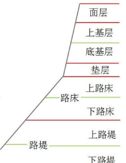
Figure 14 schematic diagram of pavement structure of road
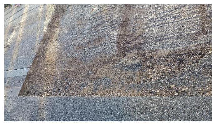
Figure 15 site drawing of subgrade and pavement structure
5. Practice experience
The production practice ended. During this period, I have gained a lot of harvest and experience, and accumulated a lot of useful experience for future work.
In the past, learning always stayed in books. There was a feeling of "getting shallow on paper". Practice can make us feel the charm of "knowing this and doing it". Practice is actually a good opportunity to combine theory with practice, and it is also an opportunity to exercise personal ability.
Because I didn't take the course of subgrade, pavement and bridge before, I felt very hard at the beginning of my internship. I can't answer the questions asked by the teacher, and I haven't even heard of some professional terms. But I still tried to listen to the discussion and explanation of teachers and students, which also enabled me to learn a lot of knowledge and see a lot of things I haven't seen. For example, I learned about pile casing, acoustic pipe, mud retaining wall, retaining wall, slope protection, how to drive piles, how to push asphalt, the role of "grid net" under asphalt and so on, And I believe that this knowledge is not memorized by rote, but learned through personal observation, which is bound to have a deeper understanding.
Generally speaking, the environment of the construction site is difficult and we are tired, but we help each other and solve problems together, which makes me very happy and enjoy, and each of us has gained a lot!
Recommended for you
A New Paradigm for Exploiting Pre-trained Model Hubs
A New Paradigm for Exploiting Pre-trained Model Hubs
It is often overlooked that the number of models in pre-trained model hubs is scaling up very fast. As a result, pre-trained model hubs are popular but under-exploited. Here a new paradigm is advocated to sufficiently exploit pre-trained model hubs.
