The Smart Fire Extinguisher - A Sprinkler System Alternative for Early Fire Detection and Prevention
UC Berkeley Mechanical Engineering, 12/11/21
By Jake Whinnery and Jake Nuesca
Applications:
The basics of why this is a useful product can be found in the fact that sprinkler systems are costly to install, rely on a separate water system, and if a false positive occurs, cost is high. This is because everything in the room, if not the building is drenched in water. Additionally, as traditional fire alarms rely on smoke detectors, the fire has likely already grown to a larger size than preferred by the time an alarm is triggered.
The smart fire extinguisher addresses those concerns by having a compact module which can be placed anywhere in a building (or attached to the ceiling) and activated. From there, it uses computer vision to detect fires, giving earlier detection, a lower cost of installation and less damage from false positives. Using computer vision also allows it to double as a security feed, be calibrated to its specific environment to prevent false positives, and detect whether a human is or recently was in the room when the fire starts. Because detection is much earlier, it can also broadcast a message to someone prior to actuating to make sure there is in fact an issue, and if no one shows up it can put out the fire.
The main applications for such a technology (at least initially until the algorithm and computer vision can be improved) would be implementation into elderly homes or other areas with high fire danger. Putting them in schools or places with electronic equipment would also be a valuable upgrade. Implementation into the smart kitchen or above a stove in the smart home is an appropriate use case as well.
Building It:
This project was broken down into a few basic milestones which needed to be completed in order to have a functional prototype.
- Need to have a live camera feed.
- Need to be able to detect a fire and output its location.
- Location needs to be received by the ESP-32.
- ESP-32 needs to orient the fire extinguisher towards the fire.
- ESP-32 needs to actuate the fire extinguisher and put out the fire.
Step 1: Stream a live camera feed.
Various cameras were investigated for different costs. In the end, the ESP-32 CAM by AI THINKER was chosen due to its low cost ($10). This milestone was actually fairly difficult to accomplish as I failed to purchase an FTDI programmer and the board does not have a USB input. Luckily, after a long and arduous attempt, I was able to flash the code onto the ESP-32 Cam using an Arduino Nano that I had on hand with its transmit and receive pins, the only issue being that this makes it very difficult to debug when the camera fails to connect to wifi. Code for getting it to connect to wifi and transmit images is displayed below. Note: capable of transmitting several different resolutions, low resolution was chosen to improve latency in this case - higher resolution should improve fire detection at greater distances.


The ESP-32 Cam, once connected to WiFi, would push a series of images to a local IP address which my computer was able to access. From there, I was able to write a Python script capable of streaming those images.
Step 2: Detect a fire and output its location.
This was a somewhat daunting step initially, as I previously had zero experience with computer vision. Through a few tutorials online, I was able to use OpenCV to start trying to detect fire. After learning a little bit about color theory and HSV, I initially attempted to filter based on color. I assumed that fire would have a warmer hue than an LED light from a camera for instance. Unfortunately, it quickly became clear that the camera in its low resolution state could not detect such a slight change in color. I used a tuning program with sliders for each of the Hue, Saturation, Value parameters and tuned to filter based primarily on the value parameter being between 235 and 255. Hue and saturation were each set to be between 0 and 50 though those parameters did not appear to have a large effect. Because of early detection, I was also able to filter based on size which helped prevent detection of flashlights. From there, it was relatively simple to find the centroid of the detected area. Code is below.


One thing that was strangely difficult, was actually figuring out how to publish info from this script to IFTTT. There was terribly low amounts of documentation for this online, and most of them actually failed to connect properly. This took probably 5-10 hours alone. I was at my wits end, reading through every function in the Paho MQTT Client library when I found it:
mqtt.username_pw_set(adafruitUsername, password=adafruitAioKey)
Centroid location was given in pixel numbers, so I needed a way to map from pixel numbers to an integer which I could feed to the ESP-32 which would convert that number to a certain amount of servo rotation. I decided to do this by using the variables split height and split width to split the screen into an 8x8 grid (higher resolution could be achieved but is not really necessary, in fact the split was originally a 4x4 grid but I decided to increase resolution once I switched from hardcoded to algorithm). Each grid had a number labeled 1-64. I was able to convert from pixel x and pixel y to a box number using this following line of code:
centroidNum = int(math.floor(cy/quadHeight)*splitWidth + math.floor(cx/quadWidth) + 1)
Needless to say, it took some time to get that line of code correct and also some whiteboarding to figure it out mathematically. From there I decided to improve the UI by boxing the rectangle as can be seen here (this also required lots of whiteboarding and tweaking to get correct):
cv2.rectangle(frame,(int(math.floor(cx/quadWidth)*quadWidth), int(math.floor(cy/quadHeight)*quadHeight)),
(int(math.floor(cx/quadWidth)*quadWidth+quadWidth), int(math.floor(cy/quadHeight)*quadHeight+quadHeight)), (0, 255, 0), 5)
The program then publishes the centroid number (if it has not published a number in the last 50 iterations - to prevent saturating the line) to the IFTTT feed, “Prometheus” that I set up.
Additionally of note, I set up an IFTTT dashboard for debugging and calibration, but the number pad only goes 1-9 which fails to capture the full range of motion (or even close to it). For that reason I wrote a separate script that I can input a number to be published. Code is below:

Step 3: Location needs to be received by the ESP-32.
This step was also not as straightforward as I originally expected primarily due to some issues with topic formatting and syntax. There was also an issue with decoding the ASCII values as I was originally just subtracting 48 from whatever value came over the subscription feed to convert from ASCII to int, but that only works for digits 0-9. I then found the .decode() function and used that instead.
Step 4: ESP-32 needs to orient the fire extinguisher towards the fire.
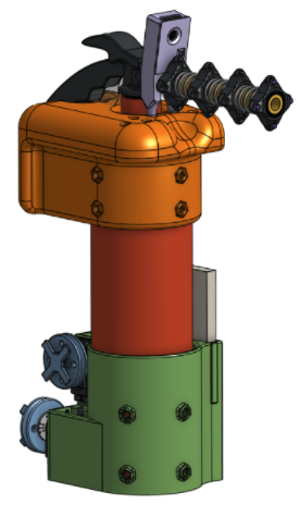
There was quite a bit of mechanical design that went into this. Rev1 design can be seen below:

I was initially not committed to using a fire extinguisher itself, so it is modeled in as some sort of pressure/water tank. This meant that an additional valve would have to be incorporated, and ideally, some way to tell how high the tank pressure is. It quickly became apparent that it would be far cheaper to buy and adapt a small fire extinguisher than it would be to buy a pressure tank, valve, and pressure regulator. The fire extinguisher itself was only $20 on Amazon.

Another issue with the first revision design is that these linkages are not easily printable without supports. While it worked for proof of concept, more space was desired between linkages, so a switch to compression based springs rather than tension was made.
Design inspiration for this mechanism was drawn largely from the borescope, the idea being to abstract the motors and mechanisms to a separate location than the actuation. This serves two main purposes: it allows greater flexibility in compact packaging and abstracts electronics away from the water or dry chemicals. This helps make the system reusable and prevents the need for water proofing.
The next revision used updated linkages with a slot for a compression spring to slide into and four holes for attachment and wire alignment. This same linkage design was carried through to final design with some add-ons for tuning.

Revision 2 design incorporated three servos placed at the base of the fire extinguisher along with the breadboard. Each servo had a copper wire wrapped around it and attached to the lead linkage.
An issue with this design was that range of motion was limited due to the low radius of attachment to the servos. Additionally, the copper wires were merely pushed against the body of the fire extinguisher, reducing repeatability. It was also difficult to tune the tension of the copper wires as they were prone to slippage when put under tension. Rotation of the fire extinguisher relative to the base was also not constrained. Regardless, it became apparent that a third revision was going to be needed.
In the third revision, the main things to address were: repeatability, tension/tuning, actuation of the extinguisher, constrained rotation, camera integration, range of motion, repressurizing the fire extinguisher, serviceability (refill the fire extinguisher), and calibration among other things. Certainly this was a tall order, and it took a couple hardware iterations to improve to the point where these issues were addressed. Luckily 3D printing enables such things to be done at relatively low cost, and total cost of filament for this project (including scrapped prints from previous revisions) probably ended up near $30.
To address repeatability, a top sleeve was added to guide the wires and orient them perfectly for the servos. This took a couple iterations to get right due to the close clearance with the release valve and extinguisher geometry.

Tension was taken care of through an ingenious breakaway support design. Designed to be a single piece, after printing, the tensioner could be broken from the other part and allowed to spin freely. This allows a single wire to be used and looped from the top of the lead linkage to the bottom. It also allows for rapid, repeatable, and adjustable tensioning. Designed through an intensive and iterative whiteboarding session as well as multiple hardware iterations, this single piece made it significantly easier to take apart, fill, pressurize, and calibrate the system efficiently. Their larger radius provided a significant improvement in range of motion as well.

Setting the servos to hold their middle position was also key for consistent tuning, so a tuning script used for this purpose is shown below:

Tuning using copper wires also proved to be difficult. Though the slippage issue was mitigated using the purple tension pegs shown below, the wires make some very sharp turns after reaching the base linkage. Without an extreme amount of tension, the wires fail to deform, drastically reducing repeatability. For that reason, a switch was made to fishing line. It is much thinner, lower friction, and bends significantly easier. It is the perfect material for this application. This also improved ease of tunability using the wire spools shown previously.

After switching to fishing line, it was not a far jump to decide to use fishing hooks instead of tuning pegs. This is because the pegs, though fairly effective for copper, still allowed slippage for the thinner, lower friction fishing line. The palomar knot was used on the fish hooks from personal experience to prevent this and worked marvelously. The switch to fish hooks also helped make it possible to service the extinguisher in an expedient manner.

Constrained rotation was accomplished through the use of nut traps (shown below) on the interior face of the part and a generic M4 screw acting as a set screw. This is a technique I have used before as a poor man’s PLA set screw and it generally works very well though joint relaxation due to PLA creep over time can be a problem. The counter bore on the exterior hides the set screw somewhat and is purely for aesthetics.

Repressurising the fire extinguisher was accomplished via some tubeless tire valves and a half inch hole drilled into the fire extinguisher (deburred thoroughly to prevent grommet damage or leakage). This was definitely a risky move, as a non-uniformity in a pressure vessel can cause stress concentration and potentially a catastrophic rupture (dangerous). However, I had sufficient confidence to carry out this step for a few reasons. For one, the fire extinguisher is rated up to 100 psi, but as a safety critical system has been tested up to 300 psi. Filling the fire extinguisher up to only 75 psi gives a relatively high safety factor given that the extinguisher is capable of holding some amount of pressure higher than 300 psi. I would have liked to perform some FEA on the part to verify what pressure it should be able to hold up to, but I have also pressurized a fire extinguisher using this method on a previous occasion (for my own nefarious purposes) after doing some hand calculations, and it did not blow up, so it can be semi-reasonably safe to assume that it would not blow here either (safety precautions were taken the first time pressurizing regardless). In order to insert the tire valve, a string was attached to the end of it, then fed through the top of the extinguisher to the drilled out hole. By pulling it through the hole, the grommet can seal from the inner surface so that we may access the outside with a generic Schrader valve attachment.
Having only a very small bike pump actually ended up being a problem as we were unable to bring the extinguisher to 75 psi in any reasonable amount of time. Eventually, I was able to jerry rig a system by hooking up our air compressor to the miniaturized bike pump in series.
One problem with the fire extinguisher being so compact, is that it can only spray for about 5-10 seconds before running out of fluid. This makes quick serviceability a must. Through intentful design though, the overall reload time was brought down to about ten minutes, requiring the following steps:
- Unscrew set screws
- Unhook fish hooks
- Undo tensioning spools and release excess fishing line
- Remove actuator pin
- Remove extinguisher from base
- Unscrew bottom of extinguisher from top nozzle
- Fill with water
- Screw into top nozzle
- Put extinguisher back into base
- Reattach fish hooks
- Screw back in set screws
- Run tuning script
- Re-tension lines
- Pin actuator to prevent accidental spray
- Pressurize vessel
Future iterations of the design should have the base and top sleeve combined into a single piece to eliminate the vast majority of steps. A larger printer and more filament may be needed as a side effect, but the change would certainly be worth it.
Camera integration was performed through a box pushing into the upper sleeve. The box had holes for pinout of the camera for power and debugging and constrained the camera at a ten degree angle downwards relative to the fire extinguisher nozzle.

Actuation of the fire extinguisher was originally accomplished using the same servo spool, but it was quickly found that the fire extinguisher requires a relatively high amount of force to actuate. To fix this, a miniaturized spool was designed. This is because the servo is capable of outputting a max torque. Torque is force times displacement, so by reducing the displacement (radius in this case), force could be increased for a fixed torque.

While this worked decently well, the fishing line was not strong enough to withstand the increased force (10 lb line is all I had on hand), so I braided three lines together and this seemed to hold up well. Despite all these changes, the servo still was not able to actuate the fire extinguisher fully, so two rubber bands were added on the actuation handle to pretension the extinguisher downwards. After implementing these steps, the extinguisher was finally able to be sufficiently actuated via the servo. Future changes to the project should definitely implement a solenoid based actuation method as this would eliminate many inconsistencies in actuation and provide a faster full actuation than the servo does in addition to likely eliminating the need for elastic pretension.
Full pictures can be found below:


To test and showoff full range of motion, I created a script as shown below:
![image]()
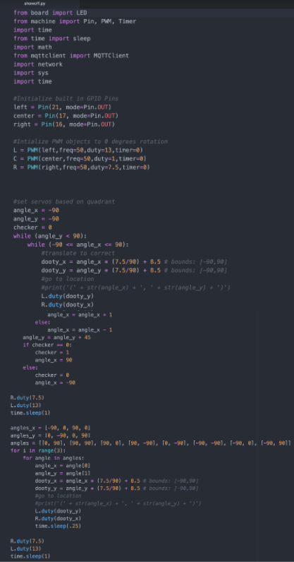
Step 5: ESP-32 needs to actuate the fire extinguisher and put out the fire.
Final integration software can be shown below, in which the ESP32 subscribes to the feed, decodes the values, maps the number to a location, maps the location to a set of servo duty cycles, rotates to that position, actuates for two seconds, stops actuating, and returns to resting position.


Some notes on the above script:
The following variables set the camera field of view bounds. These were determined experimentally, but can also be used to act as software tuning if inaccuracies are detected from prior tuning.

The bias offset brings all these values positive for use in the algorithm and corresponding translation to servo rotation.

These variables help to set the resolution variables shown below which will be used in our algorithm later.

Both mapping conversions are shown below:

Future improvements:
This was a very gratifying project to see come together, but there are many things that can be improved as listed below (which I may or may not implement in the future):
- Not enough wire organization, make a PCB and solder connections. Hide wires in print.
- Combine top and bottom sleeves for significantly quicker serviceability.
- Refine computer vision parameters to be more selective towards fire, it currently has a big problem with natural light. This can most easily be done by just using an IR camera instead of a regular one, though the price will go from ~$10 to ~$80.
- Eliminate the use of IoT at all. Though computation is expensive and better on a full computer, using a free IoT service such as IFTTT limits publish statements to 1 Hz. Instead, either use the camera to actuate the servos directly or hook it up using an I2C connection to the ESP32 in order to bypass IFTTT throttling. This will require downloading several libraries into the ESP32 boot memory, and if it doesn’t have sufficient flash memory, then upgrade microcontrollers.
- Change to battery power. This will eliminate the need to have a computer and allow it to be a standalone unit.
- Change actuation strategy from servo to solenoid. I originally wanted it to be solenoid based, but we ran out of time and I failed to clearly communicate my ideas (in a few instances). Servos work well enough for control, but this actuation, we want to be fully on, or fully off. A solenoid is much better suited for this application though it may need a decently high travel range, so a lever may need to be used.
- Improve computer vision algorithm to have a calibration period where the user guarantees there will be no fires for a day or week, to eliminate any reflections or effects of the room from triggering the extinguisher in the long run. Movement could also be detected so that the fire isn’t put out if a person is there or commands it to remain inactive.
- Using a vacuum or having some way to refill the extinguisher without taking it out would make servicing much easier as well.
- Having a standalone wifi module attached to the system so that no code changes are required to get the camera and ESP32 to connect at a new location.
- Potentially add some cooling to the camera via heatsink as latency degrades as the camera heats up.
- Add a user interface and LED screen.
- Use fishing line clip instead of a hook as the hooks occasionally come unclipped when brought to full range of motion.
- Use fisheye lens on camera. This will enable a wider field of view to take advantage of the larger area of travel of the borescope system. Some image processing may be necessary in order to fix fisheye distortion and keep accuracy of identified location high.
- Further improve aiming resolution (by changing variables already set) once repeatability improves.
Summary Video and Demonstration:
https://drive.google.com/file/d/19WvAoOwT1wgfRTlDKXIP3GI5vcPHrB6L/view?usp=sharing
Report written by Jake Whinnery
Video by Jake Nuesca